Profile Center Line:
The Profile Center Line (PCL) is an imaginary reference line used in aerodynamics and fluid dynamics to characterize the shape and geometry of an airfoil or wing profile. This line is created by joining the midpoints of the profile, starting from the leading edge (front edge) and extending to the trailing edge (rear edge) of the airfoil or wing.
Here’s a more detailed breakdown:
- Leading Edge: The front edge of an airfoil is known as the leading edge. The Profile Center Line starts at the midpoint of this leading edge.
- Midpoints: The Profile Center Line is established by connecting the midpoints of the airfoil or wing profile. These midpoints are determined by finding the halfway point between the upper and lower surfaces of the airfoil at various sections along its span.
- Trailing Edge: The rear edge of an airfoil is called the trailing edge. The Profile Center Line extends up to the midpoint of the trailing edge.
- Imaginary Line: The Profile Center Line is not a physical line on the airfoil but is a conceptual or imaginary reference line used for analysis and comparison purposes.
This reference line is particularly useful for studying the aerodynamic properties of airfoils. The shape and curvature of the airfoil can be described in terms of its deviation from the straight Profile Center Line. Engineers and aerodynamicists often use the PCL to quantify and analyze key aerodynamic characteristics, such as lift, drag, and pitching moments, which play a crucial role in the performance of aircraft and other aerodynamic devices.
In summary, the Profile Center Line is a vital tool in aerodynamics, providing a standardized reference for characterizing and analyzing the shape of airfoils or wing profiles.
To know about Camber: Click Here
To know about Chord line: Click Here
To know about Angle of Attack: Click Here
What is profile center line example?
To better illustrate the concept of the Profile Center Line (PCL), let’s consider a simplified example of an airfoil. For this example, we’ll use a NACA 2412 airfoil, which is a commonly used airfoil in aerodynamics.
The NACA 2412 airfoil is defined by a set of coordinates specifying the shape of the upper and lower surfaces at various points along its span. The Profile Center Line is then created by connecting the midpoints between the upper and lower surfaces.
Here’s a basic representation of the NACA 2412 airfoil and its Profile Center Line:
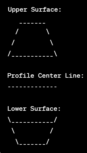
In this diagram:
- The upper surface of the airfoil is represented by the top curved line.
- The lower surface is represented by the bottom curved line.
- The Profile Center Line is represented by the horizontal dashed line connecting the midpoints between the upper and lower surfaces.
Please note that this is a highly simplified and schematic representation for illustrative purposes. In reality, the airfoil’s shape is defined by more complex coordinates, and the Profile Center Line is a continuous imaginary reference line joining the midpoints at various sections along the airfoil span.
Understanding the Profile Center Line helps in analyzing the airfoil’s aerodynamic characteristics, such as lift and drag, by providing a standardized reference for measuring deviations in the airfoil’s shape.
How to measure profile of a surface in CMM?
A Coordinate Measuring Machine (CMM) is a precision measurement device used for dimensional inspection of physical objects. To measure the profile of a surface using a CMM, you can follow these general steps:
- Preparation:
- Ensure that the CMM is calibrated and its probe is in good condition.
- Secure the workpiece on the CMM’s measuring platform or fixture.
- Programming:
- Create a measurement program using CMM software. This involves defining the measurement path, probe orientations, and any required measurement strategies.
- Specify the measurement parameters, such as the measurement speed, point density, and scanning mode.
- Probe Selection:
- Choose an appropriate probe for the measurement task. Different probes may be suitable for various types of surfaces (e.g., touch probes, scanning probes, laser probes).
- Datum Establishment:
- Establish a reference or datum point on the workpiece. This is crucial for accurate measurements. It may involve touching the probe to specific features on the part to set the origin and orientation.
- Surface Measurement:
- Execute the measurement program on the CMM. The probe will move along the defined path, collecting data points on the surface.
- Scanning (if applicable):
- If the CMM has a scanning capability, the probe may move continuously along the surface, capturing a series of data points to create a more detailed profile.
- Data Analysis:
- Once the measurement is complete, the CMM software will generate a point cloud or data set representing the measured surface.
- Use the software tools to analyze the data, extract relevant profile information, and compare it with the nominal or desired profile.
- Reporting:
- Generate measurement reports detailing the deviations from the nominal profile, if any.
- Include key metrics such as form errors, dimensional tolerances, and surface roughness, depending on the measurement requirements.
- Verification:
- Verify the accuracy and repeatability of the measurements. Ensure that the measured results meet the required specifications.
It’s important to note that the specific steps and features available can vary depending on the CMM model and software used. Always refer to the CMM manufacturer’s documentation and guidelines for the most accurate and reliable measurements. Additionally, training in CMM operation and programming is crucial for obtaining accurate and meaningful results.