Inversion Of Four Bar Chain
Inversion of four bar chain: In this article we will learn about Inversion of four bar chain.
There are many Different types of inversions of the four bar chain, the detailed explanation about Inversion of four bar chain is explained as Follows.Four bar chain mechanism is the simplest than many other types of closed mechanisms. this type of mechanism has four links in which three are movable links and one is a fixed link. With the help of different links in a kinematic chain process, we can get/obtain different types of inversions of four bar chain mechanisms.
Different types of Inversion of four bar chain are Beam Engine, Coupling rod of locomotive, Double lever mechanism.
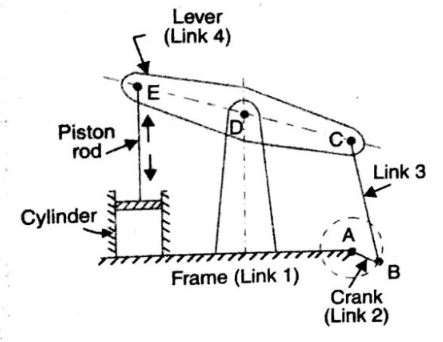
1) BEAM ENGINE(CRANK AND LIVER MECHANISM)
The main purpose of Beam engine is used to convert the rotary motion in to reciprocating motion. It is a part of the mechanism of a beam engine this is also known as Crank and liver mechanism, which consist of four links, in this mechanism when the Crank rotates about a fixed center A , the liver oscillates about a fixed center D the end E of the liver CDE is connected to the position rod which reciprocates due to the rotation of the crank. .
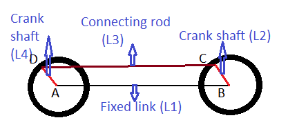
2) COUPLING ROD OF A LOCOMOTIVE (DOUBLE CRANK MECHANISM):
The mechanism of a locomotive/double crank contains four links which are AB, BC, CD and AD. In this links AB link is a fixed one, both AB and BC links acts as Crank. and Link CD acts as Coupling rod. Fixed link of AB maintains constant distance from one center of circle to next center of circle. This type of mechanism is used to transfer the motion from one wheel to the next wheel, the motion transfer one wheel to another wheel is a rotary motion, which helps in moving the vehicle.
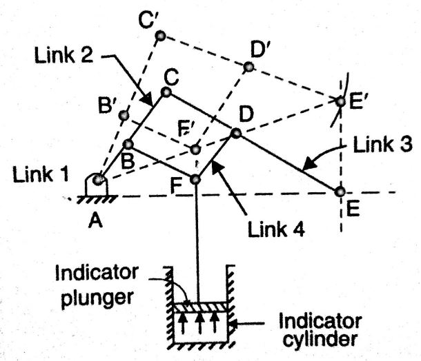
DOUBLE LEVER MECHANISM(WATT’S INDICATOR MECHANISM):
A WATT’S indicator mechanism which consist of four links, the four links are A, AC, CE and BFD. The displacement of the link BFD is directly proportional to the gas or steam pressure, this pressure of gas/steam used act on the indicator plunger. complete/clear lines indicates the position at starting time of mechanism and the dotted lines represents the position when the gas/steam pressure acts on indicator plunger.
The link E used move upwards when indicator plunger raises by the help of gas pressure, and the remaining links used to change there position according pressure act on indicator plunger.
Please Subscribe! and Don’t forget to Follow us on Facebook, Twitter, Linkedin, Instagram and Google Plus.